
| Summary: When is 3D CFD required in gas dispersion modelling? 3D CFD isn’t usually named as a legal requirement. UK and Australian rules apply the ALARP principle instead; US rules ask for a documented hazard analysis; Norway’s NORSOK standards build CFD into recognised offshore practice, though they’re industry standards, not statutes. In practice, CFD becomes necessary once site geometry — congested modules, offshore/FPSO topsides, partial confinement, complex terrain — means a simpler integral model can’t give a defensible result. Open, unobstructed sites are usually well served by integral screening instead. |
Why Model Selection Is a Project Decision, Not Just a Software Decision
Ask five process safety engineers when a project needs 3D CFD gas dispersion modelling, and you’ll get five different answers. That’s not disagreement about physics — it’s because the decision rarely comes down to software alone.
DNV PHAST can run a case in minutes. Gexcon FLACS or DNV KFX often take much longer once geometry and meshing are built. Both are correct tools, for different questions. A screening QRA comparing several layouts needs speed. A detailed check on whether gas can reach an HVAC intake through a congested module needs more spatial accuracy than a simple model gives.
Treating this as a software choice causes two mistakes: defaulting to the fast, familiar method and missing real congestion effects, or running full CFD on every case and wasting budget where a simpler model would do just as well.
The better approach ties model choice to three things: site geometry, the question being asked, and the project phase.
Legal Requirement vs Technical Justification
Most process safety rules ask for a documented, defensible assessment — not a named method like CFD.
In the UK and Australia, this sits under the ALARP principle: reduce risk as low as reasonably practicable. It’s central to COMAH, the UK Offshore Safety Case Regulations, and Australia’s NOPSEMA regime. US rules differ: OSHA’s PSM standard and EPA’s RMP don’t use ALARP language at all — they ask for a documented hazard analysis instead. The EU’s Seveso III Directive asks for a safety report on major-accident prevention, again without naming a specific model.
Norway is a partial exception. NORSOK C-004 and Z-013 are industry standards, not laws. Norway’s Petroleum Safety Authority runs a goal-based regime, and applying these standards is the accepted way to show compliance. C-004 calls for CFD-based hot gas dispersion modelling on helidecks; Z-013 uses CFD for ventilation, dispersion, and explosion as separate steps. Because operators apply them so consistently, CFD is the practical norm offshore Norway, even though the standards aren’t statutes.
Elsewhere, the real question isn’t “does a rule name CFD?” It’s “would a simpler model hold up if challenged?” If a congested site makes that answer no, CFD becomes necessary in practice.
When an Integral or Phenomenological Model Is Normally Adequate
Not every release needs a 3D study. Most early screening work shouldn’t use CFD at all.
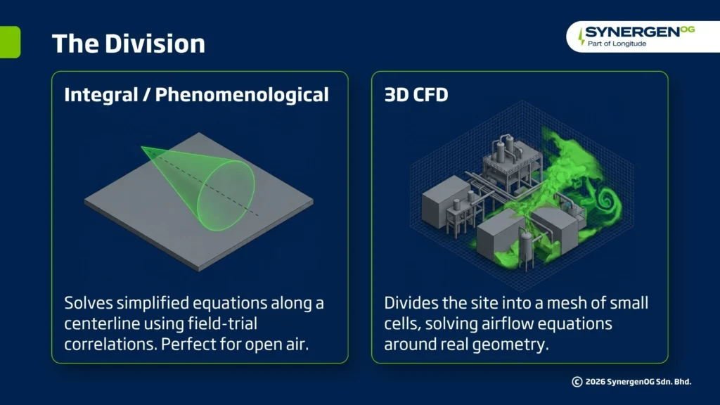
Tools like DNV PHAST are often called “2D models,” but that’s not quite right. They’re integral or phenomenological models: they solve simplified equations along a plume’s centerline, using correlations from decades of field trials, rather than resolving a full 3D flow field. That’s their strength — speed and a strong validation base — and their limit: no representation of individual obstacles.
These models work well when a release travels through open air with little to interfere with it. That’s exactly the case they’re built for.
Integral tools are a reasonable choice for early screening across many scenarios, open flat sites with equipment spaced well apart, regulatory look-up methods such as EPA RMP screening, and toxic dispersion over open terrain.
If your site is genuinely open and the question is “roughly how far could this go,” an integral model is usually enough. The harder calls start when geometry enters the picture.
10 Project Conditions That May Justify 3D CFD
Once geometry, confinement, or consequence sensitivity enter the picture, integral models lose reliability. These ten conditions commonly point toward 3D CFD. Treat them as prompts to check against your site, not a checklist where one hit makes CFD automatic.
1. Offshore platform or FPSO
Topside modules, decks, and hull structures redirect wind in ways an integral model can’t capture. NORSOK Z-013 builds CFD into its offshore methodology. Not every module is equally congested, though — an isolated open deck may still suit an integral model.
2. Congested process modules
Pipe racks, compressors, and exchangers create turbulence that can trap gas or help it disperse. Engineers often assess this with metrics like volume blockage ratio, though no single percentage triggers CFD alone — thresholds depend on the methodology used, so check them against your own risk basis.
3. Partial confinement
Decks and walls change how gas behaves. Grated decks vent gas vertically; plated decks trap it. An integral model can’t represent that difference.
4. Buildings and occupied structures nearby
The question here is whether a cloud can reach or be drawn into a nearby building through doors, gaps, or an HVAC intake. Integral models built on open-terrain assumptions can miss how a structure disrupts airflow. Whether the building could survive an explosion is a separate study.
5. Complex terrain
Sloped pipe racks, elevated bridges, or uneven ground change where heavy gas settles. A flat-terrain model misses pooling in low points, often exactly where people or ignition sources are.
6. Dense or low-momentum releases
Cold, heavy vapors and low-pressure leaks lack the momentum to punch through obstacles. They hug the ground and follow the geometry, which simplified plume-shape models capture less precisely.
7. HVAC intake assessment
If a cloud can reach a control room or accommodation intake, you need the real airflow path, not just a downwind distance. CFD answers that better than a centerline-based model.
8. Gas detector optimisation
Detector placement depends on where gas is likely to accumulate, which depends on local geometry. CFD is a common method for detector mapping in congested areas; simple radius rules suit open areas better.
9. Indoor or enclosed releases
Enclosed rooms rely on mechanical ventilation, not free wind, so open-air assumptions don’t apply. A small, well-ventilated room can often be checked with a basic ventilation calculation. CFD earns its place once the geometry is complex or dead zones are a real risk.
10. Results close to acceptance criteria
Integral models carry built-in conservatism. When a result sits close to your risk threshold, that conservatism can trigger costly design changes that may not be needed. CFD earns its cost here because it can change the decision, not just refine the number.
Decision Matrix: Integral Screening, Hybrid Assessment, or Full CFD
Most projects don’t face a clean choice between integral and CFD. Teams often use a hybrid approach: screen broadly with an integral model, then run CFD only where it matters.
| Factor | Integral Screening | Hybrid Assessment | Full 3D CFD |
| Site type | Open, flat, unobstructed | Mixed – some congestion, some open areas | Congested, confined, or offshore/FPSO |
| Question asked | “Roughly how far could this travel?” | “Which scenarios need closer review?” | “Where exactly does gas go?” |
| Number of scenarios | Many (dozens to hundreds) | Screened down to a shortlist | Few – the ones that matter most |
| Typical use | Concept selection, early QRA | FEED-stage QRA with congested sub-areas | Detector mapping, HVAC risk, building siting |
| Typical tools | DNV PHAST | PHAST for screening, FLACS/KFX for shortlist | Gexcon FLACS, DNV KFX |
| Turnaround | Hours to days | Days to a few weeks | Weeks, depending on complexity |
| Cost profile | Low | Moderate | Higher, but targeted |
This keeps the cost proportional to risk instead of using the most expensive method everywhere. One exception: heavily congested offshore or FPSO topsides often go straight to CFD, since congestion there is usually the norm. Even then, a short screening pass can help prioritise which scenarios need the closest attention.
Read: FPSO Safety – The Role of PSM
Model Selection by Project Phase
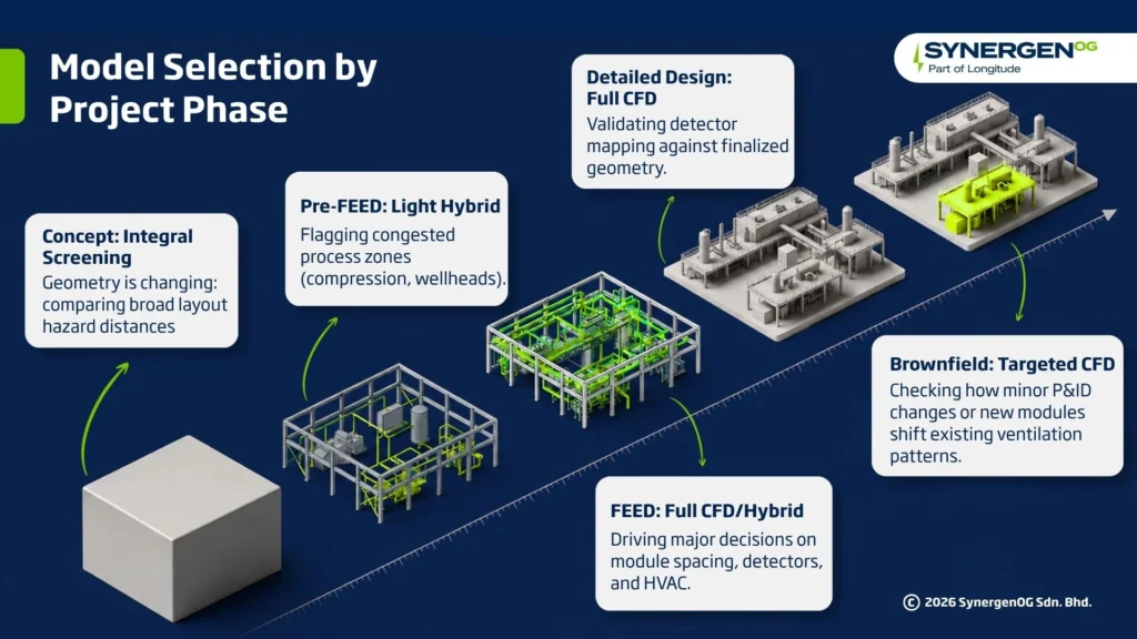
The right model also depends on where you are in the project lifecycle.
Concept Selection
Layout options, or even different platform concepts, are still being compared. Geometry isn’t final, so detailed CFD would model something about to change. Integral screening across concepts gives fast, comparative hazard distances.
Pre-FEED
Congestion in key areas — compression, wellheads, process modules — becomes visible for the first time. A light hybrid pass here flags which zones will likely need CFD later.
FEED
Most of the ten conditions get tested properly here. CFD at FEED usually drives major decisions — module spacing, detector layout, HVAC protection — so it’s hard to avoid on congested or offshore facilities, even without a named rule requiring it. A separate explosion study may also be needed for things like blast walls.
Detailed Design
Geometry is close to final, so CFD results carry more weight. Detector mapping and HVAC protection get validated against actual positions, not assumptions.
Brownfield Modification
A new module or piping change can quietly shift ventilation patterns set years earlier. A change that looks minor on a P&ID can still justify a fresh CFD run. Management of change processes should flag this rather than assume the old study still applies.
Risks of Under-Modelling and Over-Modelling
Getting model selection wrong costs more than money — in the worst cases, it costs lives.
The Risk of Under-Modelling
Using an integral model where CFD was needed gives a result that looks complete but isn’t. The numbers may not reflect how gas actually behaves on a congested site.
One well-known example, from the explosion side of process safety rather than dispersion, is the 2005 Buncefield fuel depot explosion in the UK. The site had little process congestion, but dense trees near an access road are thought to have added unaccounted-for congestion, driving overpressures far above what standard methods predicted. The UK’s Buncefield Major Incident Investigation Board, and later research summarised by FABIG, concluded this was consistent with a deflagration-to-detonation transition. The lesson carries over: congestion isn’t always where expected, and an unchecked model assumes it for you.
Under-modelling is dangerous because it’s invisible until something goes wrong.
The Risk of Over-Modelling
The opposite failure is quieter but still costly. Full CFD on an open, uncongested site wastes budget without adding useful information, and can create false confidence simply because it took longer and cost more.
The goal isn’t more modelling. It’s matching the method to the question.
Verification, Validation, and Uncertainty in CFD Dispersion Studies
A CFD result is a prediction, not a measurement — it comes with error, even when the output looks precise.
Verification asks whether the model is solving its equations correctly. This is checked with mesh sensitivity studies: rerunning a case at finer resolution to confirm the result stops changing. An unchecked mesh carries unknown numerical error.
Validation asks whether the model represents real physics. This means comparing predictions against independent field data, not just other simulations. Gas dispersion modelling has a strong validation base: the Thorney Island trials run by UK HSE, the Desert Tortoise, Goldfish, Burro, and Maplin Sands trials, and more recently the Jack Rabbit II chlorine trials. Both integral and CFD tools are regularly checked against this data.
In practice, a defensible study should point to a validation basis for the release type being modelled, and include a mesh sensitivity check for the geometry. This matters most when a result sits close to a decision threshold — condition 10 above.
Information Required Before Commissioning a CFD Study
A CFD study is only as good as what goes into it. Have these ready before you commission one.
Geometry and layout
- Up-to-date 3D model or as-built drawings, including equipment, piping, and decking
- What’s fixed vs. what may still change
Release scenarios
- Material, phase, and credible hole sizes, pressures, and temperatures — usually from a HAZID or HAZOP
- Release direction and duration
Environmental data
- Site wind rose and prevailing directions
- Atmospheric boundary-layer conditions (wind profile and turbulence, often based on Pasquill stability class or site data)
Study objectives
- The decision the study supports — detector placement, HVAC protection, building siting, or QRA input — and the endpoints being checked (flammable range, IDLH, overpressure)
- Whether the study covers dispersion only, or dispersion plus a separate explosion assessment
Process safety information
- P&IDs and inventory data
- Any prior studies for the same area, for consistency
Gaps here don’t stop a study — but they force assumptions a reviewer can later challenge.
Questions to Include in a Consultant’s Scope of Work
Whether you’re hiring a consultant or reviewing an internal proposal, these questions show whether the approach was actually thought through.
On method selection
- Which of the ten conditions apply to this site, and how were they identified?
- If integral screening is proposed, what congestion checks confirm it’s adequate?
- Does the scope cover dispersion only, or also explosion consequences?
On technical basis
- Which tool and module will be used, and why does it fit this geometry?
- What mesh resolution is planned, and how was it justified?
On validation
- What field-trial validation basis does the tool have for this release type?
- Has a mesh sensitivity check been run for this geometry?
- Who reviews the setup and checks the output before it’s issued?
On deliverables
- Will the study include isopleths on the facility layout, or numbers only?
- Does it link back to the specific decision it needs to support, and to the safety case where relevant?
A scope of work that can’t answer these clearly usually means the method was chosen by habit, not by fit.
Not sure whether your project needs integral screening, a hybrid approach, or full 3D CFD? SynergenOG‘s technical risk team can review your site and recommend the right method for your project phase.
References:
- https://www.hse.gov.uk/enforce/expert/index.htm
- https://www.standard.no/en/sectors/energi-og-klima/petroleum/norsok-standards/
- https://www.standard.no/en/sectors/energi-og-klima/petroleum/norsok-standard-categories/z-risk-analyses/z-0132/
- https://www.hse.gov.uk/offshore/strategy/source.htm
- https://www.fabig.com/industrial-accidents/buncefield-uk/
- https://www.gexcon.com/resources/blog/investigation-techniques-used-to-determine-the-massive-vapor-cloud-explosion-at-the-buncefield-fuel-depot/
- https://www.gexcon.com/software/flacs/
Technical Note: This article provides general technical guidance on determining when 3D CFD gas dispersion modelling may be appropriate for oil and gas facilities. The required modelling approach may vary depending on facility geometry and congestion, degree of confinement, release characteristics, fluid properties, ventilation conditions, meteorological data, receptor sensitivity, modelling objectives, and project lifecycle stage. The selection between integral consequence modelling and 3D CFD should be based on the level of physical detail required to support the specific engineering or risk decision. This guidance should be applied alongside applicable regulations, industry standards, company engineering practices, validated modelling methodologies, project-specific risk assessments, and the judgment of competent process safety and CFD professionals.