What is gas dispersion modelling in risk assessment? Dispersion analysis is the simulation of how a hazardous gas release moves, dilutes, and settles after a leak. It is a core part of quantitative risk assessment (QRA) because it helps safety teams predict toxic and flammable hazard zones, improve gas detector mapping, and support compliance and consequence modelling work.
Key Takeaways
Gas dispersion modelling helps teams understand where a gas cloud may travel, who may be exposed, and which equipment or buildings may be affected. It supports QRA, gas detector mapping, emergency planning, and facility layout decisions. The choice of tool usually depends on whether the site is simple and open or congested and complex, utilizing established software like DNV PHAST, DNV Safeti, or 3D Computational Fluid Dynamics (CFD) platforms like Gexcon FLACS.
The Gap Between Hazard and Consequence
Knowing that a pipe can leak is not enough. Process safety teams also need to know what happens after a leak begins, because the cloud path, concentration, and exposure time shape the actual consequences of the event. OSHA’s Process Safety Management (PSM) guidance is built around the control of hazards posed by highly hazardous chemicals, and QRA frameworks formally combine likelihood and consequence in a structured manner.
That is why dispersion modelling matters. It links a loss-of-containment scenario to its real impact on people, equipment, and operations by estimating how a release disperses and the resulting hazardous effects. Industry software providers such as DNV describe their consequence analysis tools as software that calculates discharge, atmospheric dispersion, and the flammable or toxic effects associated with these events.
This article explains why gas dispersion modelling is important, how gases behave under real-world conditions, when to use 2D models versus 3D CFD, and how a typical study is conducted. It also identifies the main software used in the market today for screening studies, full QRA work, and detailed CFD analysis.
Why Gas Dispersion Modelling Is Critical for Process Safety
Dispersion modelling is critical because it turns a leak scenario into usable safety decisions. It provides teams with a technical basis for estimating consequence distances, planning mitigation measures, and demonstrating that hazards have been formally evaluated.
Feeding the Quantitative Risk Assessment (QRA)
Gas dispersion modelling feeds QRA by defining the size and duration of toxic and flammable hazard zones. Because QRA is a formal and systematic approach to estimating the likelihood and consequences of hazardous events, dispersion output is a direct input to the consequence side of the analysis.
For flammable releases, the model shows where gas concentrations may enter the flammable range. For toxic releases, it indicates where exposure may exceed a selected endpoint, such as the NIOSH IDLH limit for hydrogen sulfide. Without credible consequence modelling, the picture of individual and societal risk becomes weaker and less defensible.
Optimizing Safety Critical Elements
Dispersion studies help safety systems work where they matter most. They are highly valuable for gas-detection mapping, HVAC protection, and safeguarding occupied buildings.
In gas detector mapping, the primary objective is to place detectors where gas is most likely to pass, accumulate, or remain. Gexcon specifically highlights CFD as a practical method for modelling toxic gas in complex environments, which is why 3D analysis is widely used when physical congestion affects detector performance.
The same logic applies to HVAC systems and control rooms. If a toxic or flammable cloud can reach an air intake, the intake location, isolation logic, or pressurization strategy may need to be modified to comply with safe operational limits.
Meeting Regulatory and Safety Case Expectations
Operators use dispersion analysis to prove that major hazards have been understood and assessed. OSHA’s PSM standard emphasizes the management of hazards associated with highly hazardous chemicals. At the same time, the EPA’s Risk Management Program (RMP) requires covered facilities to develop and submit an explicit plan for listed toxic or flammable substances.
In Europe, the Seveso III Directive requires operators to provide safety reports detailing dangerous substances, major-accident scenarios, risk analysis, and prevention measures, making consequence modelling highly relevant to safety case development.
Emergency Response and Evacuation Planning
Modelling improves emergency planning by showing which areas stay safe and which do not under different release and weather conditions. A route that is safe in one wind direction may be deadly in another. Because of this, dispersion results are often reviewed together with wind roses and site weather data (often using standard Pasquill stability classes) before teams finalize mustering points, escape routes, and emergency instructions.
The Physics
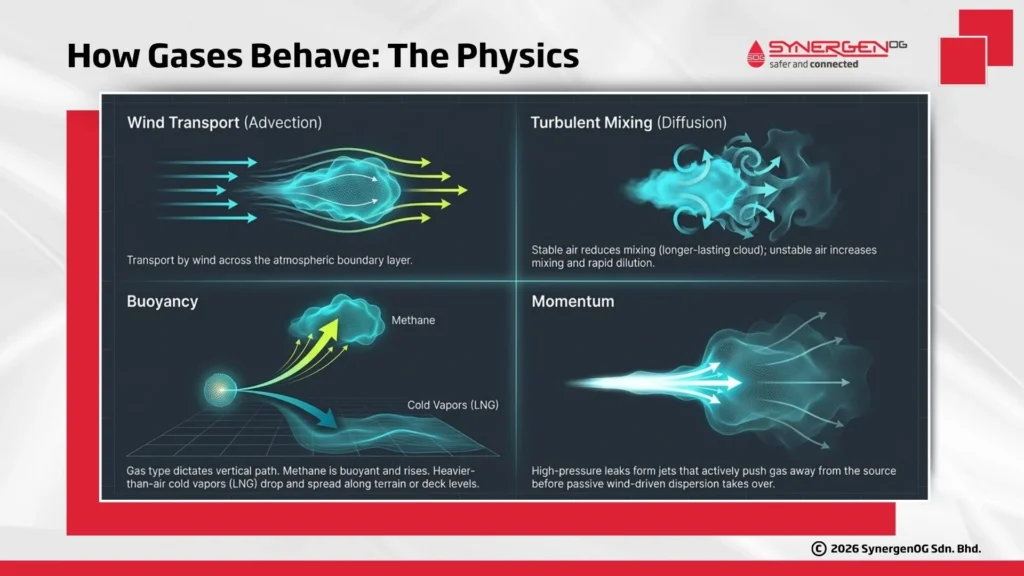
Gas clouds move according to a few basic physical processes: wind transport, turbulent mixing, buoyancy, and release momentum.
Advection is the transport of gas by the wind, while turbulent diffusion spreads and dilutes the cloud. These processes are strongly affected by the atmospheric boundary layer and atmospheric stability. Stable air usually means less mixing and a longer-lasting cloud, whereas unstable air increases mixing and often reduces concentrations more rapidly.
Gas type also changes the outcome. Methane is buoyant and often rises, while gases such as hydrogen sulfide can create severe toxic hazards (per NIOSH guidelines), and heavier-than-air cold vapors like LNG can remain low, spreading along terrain or deck levels.
Momentum matters too. A high-pressure leak can form a strong jet that pushes gas away from the source before normal wind-driven dispersion dominates, while lower-energy releases behave more like passive dispersion.
2D vs. 3D Gas Dispersion Modelling: Choosing the Right Approach
A common industry rule of thumb is to use 2D models for fast screening in simple environments, and 3D CFD for complex and congested facilities.
2D Integral and Empirical Models
2D integral models are best for speed and broad coverage. They are widely used in early screening studies because they enable engineers to evaluate numerous cases efficiently. A major market example is DNV PHAST. These tools work well when the facility is open and the terrain is simple. Their main limitation is that they do not fully capture detailed airflow around congested plant geometry.
3D Computational Fluid Dynamics (CFD)
3D CFD gas dispersion is necessary when the geometry changes the hazard. This is common on offshore platforms, FPSOs, and dense process modules where obstacles, walls, and equipment strongly affect airflow and gas build-up. CFD solves flow equations within a 3D digital model, enabling stimulation of wind flow around equipment, turbulence behind structures, and gas accumulation in confined areas. Two recognized tools in this space are Gexcon FLACS CFD and DNV KFX.
How to Execute a Dispersion Study
A dispersion study usually follows five practical steps:
- Define the Scenario and Calculate the Source Term: Start by defining the material, pressure, temperature, hole size, leak direction, and duration. Consequence models use this source term to quantify the amount of material released.
- Add Environmental and Meteorological Inputs: Define wind speed, wind direction, air temperature, and atmospheric stability.
- Build the Geometry and Mesh for 3D CFD: For 3D analysis, engineers create a digital model of the facility and divide it into many small calculation cells (a mesh) to represent airflow around modules and vessels with high realism.
- Run the Simulation: The simulation is executed for the selected release and weather cases. In CFD work, this usually means modelling the wind field first and then simulating the gas release behavior over time.
- Generate Isopleths and Perform Consequence Analysis: The final step converts model outputs into engineering decisions by generating concentration contours (isopleths) for flammable or toxic endpoints and overlaying them on the facility layout.
Industry-standard tools include DNV PHAST for consequence screening, DNV Safeti for full QRA integration, Gexcon FLACS CFD for detailed 3D studies, and DNV KFX for advanced CFD-based fire and dispersion modelling.
How SynergenOG Helps with Gas Dispersion Modelling
SynergenOG provides expert 2D and 3D gas dispersion modelling to transform complex leak scenarios into actionable safety data. We specialize in optimizing gas detector mapping, refining HVAC protection, and ensuring your facility meets strict QRA and regulatory standards.
Protect your assets and personnel, contact SynergenOG today to quantify your technical risks with industry-leading dispersion simulations.
Conclusion: Integrating Dispersion Data into the Safety Case
Gas dispersion modelling in risk assessment is a practical safety tool that helps engineers understand what happens after a leak and what actions should follow. It strengthens QRAs, improves gas detector mapping, and gives highly accurate input for emergency planning and layout design.
In open, simple areas, 2D integral dispersion models may suffice. In offshore and congested facilities, 3D CFD gas dispersion often gives the level of detail needed for confident decisions. Whether the goal is rapid screening or detailed spatial analysis, accurate consequence modelling remains a core part of a strong, compliant safety case.
References:
- https://www.gexcon.com/software/flacs/
- https://www.epa.gov/rmp
- https://www.ready.noaa.gov/READYpgclass.php
- https://www.cdc.gov/niosh/npg/npgd0337.html
- https://www.ready.noaa.gov/READYpgclass.php
Disclaimer: This article is based on the cited references.